 MyGNU.de
Unboxing the Astro Slide
Like I did when receiving the Cosmo Communicator, I want to share the first impressions while unboxing the brand new Astro Slide, I have received yesterday. About two and a half years ago I have backed Planet Computers Astro Slide Indiegogo campaign. Again Planet Computers has promised a device that is different from anything else, that is available for purchase. The Astro Slide is a slider class device with a fully integrated keyboard and touchscreen and full phone usability that is designed for Android, but will also be capable of running Linux or Sailfish OS. No need to go through the full specs here, everything interesting regarding these can be read on Planet Computers web page. Originally Planet Computers was planning the device in March 2021, then Covid-19 appeared… Yesterday, after a long time of waiting the parcel with the Astro Slide finally arrived. When receiving the parcel I had to pay an additional 33€ import fees.

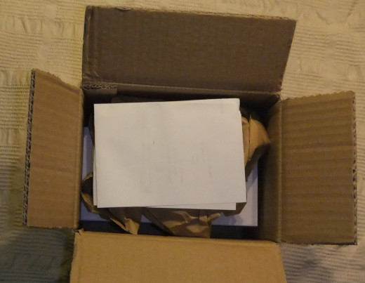
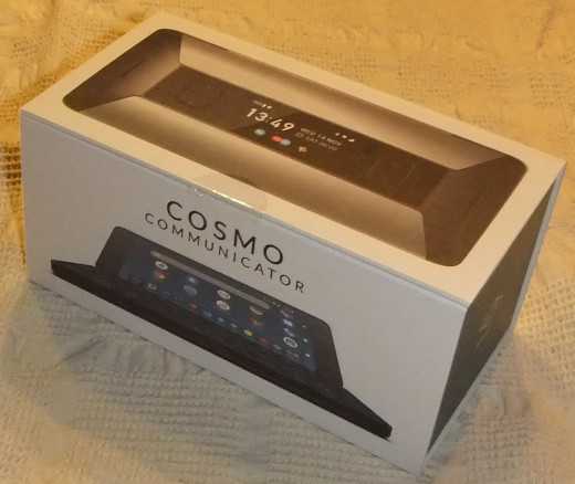
Inside the parcel has been a single box.
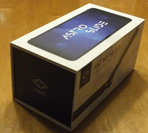
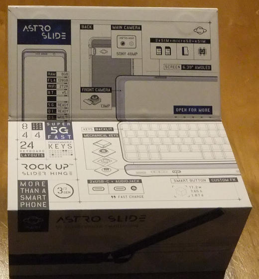
Before opening the box has to be fold out.
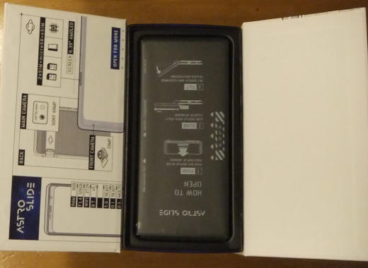
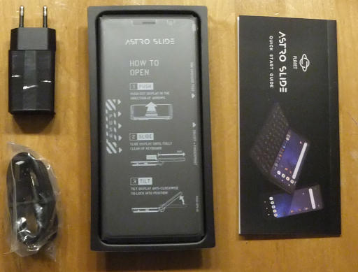
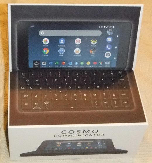
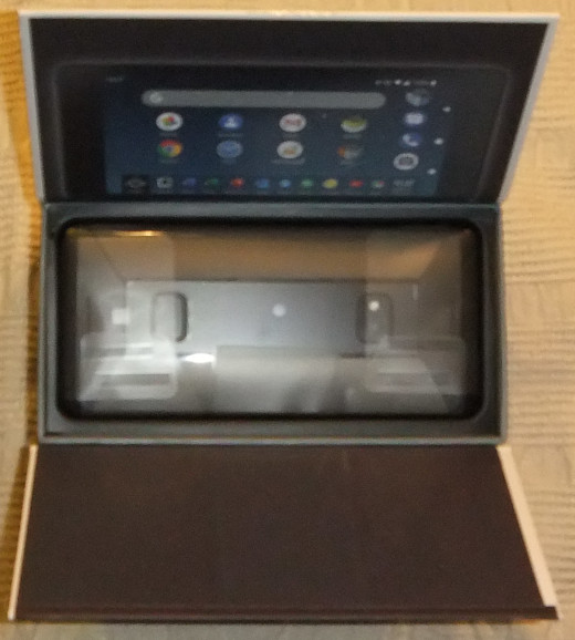
After Opening the box one can see the well packed Astro in there.
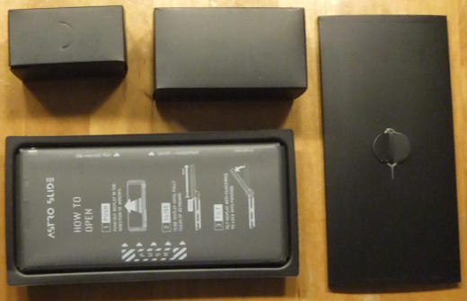
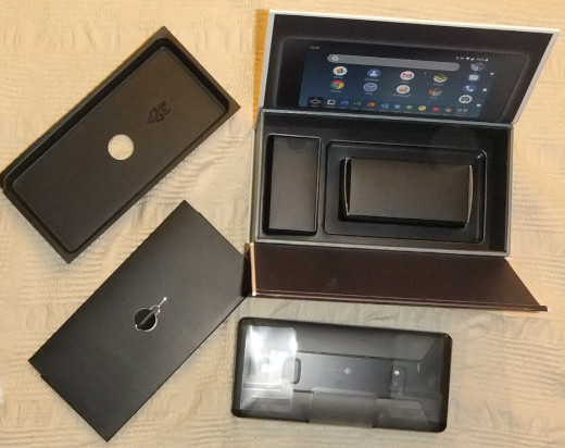
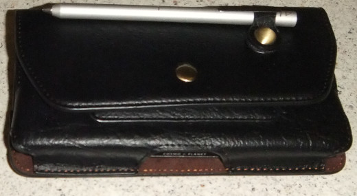
The full content of the box can be seen below. One can see the Cosmo wrapped well in foil as well as an envelope containing a quick start manual and the Sim card tool. Still in the box are two smaller boxes containing the charger and the USB cable.
After some further unboxing we can see charger and user manual.
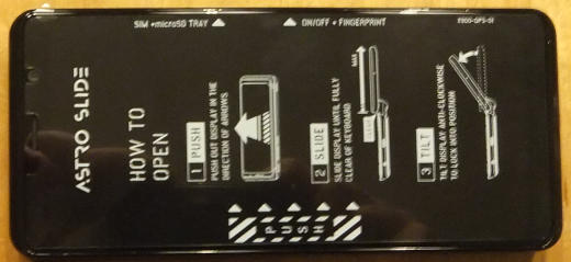
After removing the foil we can see the Astros full beauty.
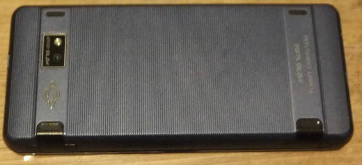
From the back side we can see camera and rubber feet.
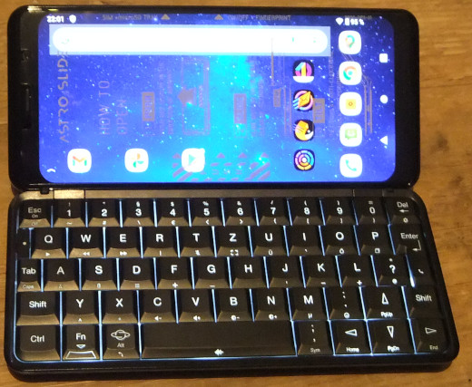
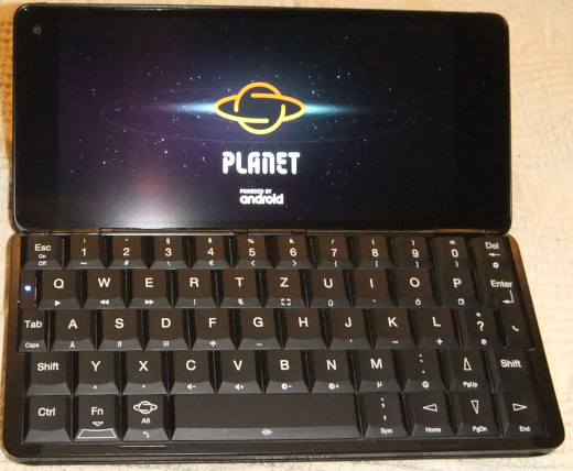
With the opened device we can see the display and the German QWERTZ keyboard. The keyboard again feels more solid as with the Cosmo.

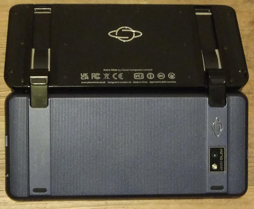
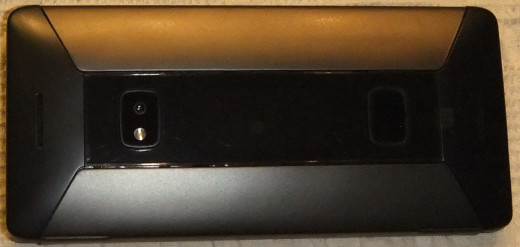
When opened we can see the sliding mechanism from the back. The sliding mechanism is a bit clumpsy as others described before. It will take some time to get the feel for it.
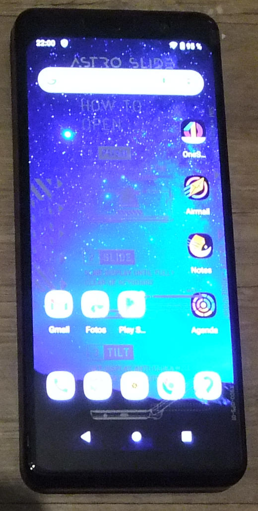
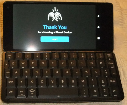
After completing the initial setup process the Astro shows the Android desktop.
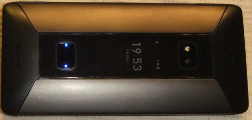
Below we can see the desktop in landscape while the keyboard is slided out and its backlit is turned on. Unfortunately the display corners are far rounder than with the Cosmo.
I am hoping you have enjoyed the photo series and some first impressions of the Cosmo. Further articles regarding testing some aspects of the device, and hopefully some solutions will follow. Stay tuned for updates.
Jürgen
 (1 votes, average: 5.00 out of 5)


![[Valid RSS]](https://validator.w3.org/feed/images/valid-rss.png "Validate my RSS feed")

